Configuring WLAN Settings

This section describes the configuration of WLAN, including enabling, creating, editing, deleting a WLAN.

Enabling a WLAN

By default, the WLAN function of the system is enabled.

To enable the WLAN function, take the following steps:

  1. On the Navigation pane, click Configuration > Network > WLAN to visit the WLAN page.
  2. Select the Enable checkbox and then click Apply.

Creating a WLAN

To create a WLAN, take the following steps:

  1. On the Navigation pane, click Configuration > Network > WLAN to visit the WLAN page.
  2. Click the New button on the top-left corner to create a WLAN.
  3. In the WLAN Configuration dialog, specify the following information:
  4. After finishing the configurations above, click OK to save the configurations.
  1. On the Navigation pane, click Configuration > Network > Network to visit the Network page.
  2. Click New on the upper-left of the interface list.
  3. Select VLAN Interface from the drop-down list.

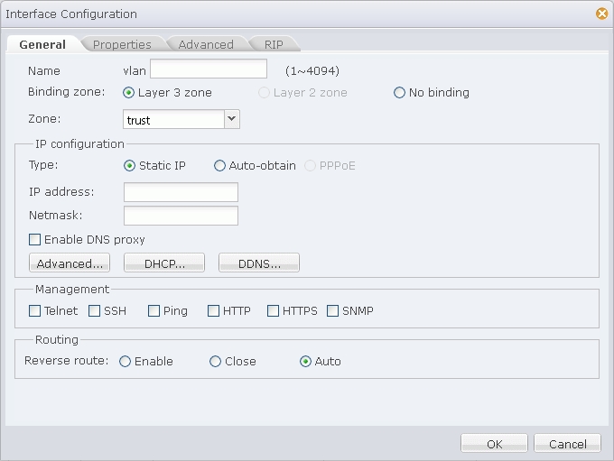
  4. In the Interface Configuration dialog shown above, specify a name. If necessary, type the description information into the Description text box.
  5. Specify the binding type. If Layer 3 zone is selected, also select a security zone from the Zone drop-down list.
  6. If Layer 3 zone is selected, in the IP Configuration section, configure IP related information for the interface. For detailed options, see the following instructions:
    Type Description
    Static IP IP address: Specifies an IP address for the interface.
    Netmask: Specifies a netmask for the interface.
    Enable DNS Proxy: Select this checkbox to enable DNS proxy for the interface.
    Advanced Management IP: Specifies a management IP for the interface. Type the IP address into the box.
    Secondary IP: Specifies secondary IPs for the interface. You can specify up to 6 secondary IP addresses.
    DHCP: In the DHCP Configuration dialog, configure DHCP related options for the interface. For detailed instructions, see Configuring DHCP.
    DDNS: In the DDNS Configuration dialog, configure DDNS related options for the interface. For detailed instructions, see Configuring a DDNS.
    Auto-obtain Set gateway information from DHCP server as the default gateway route: With this checkbox selected, StoneOS will set the gateway information provided by the DHCP server as the default gateway route.
    Advanced Distance: Specifies a route distance. The value range is 1 to 255. The default value is 1.
    Weight: Specifies a route weight. The value range is 1 to 255. The default value is 1.
    Management Priority: Specifies a priority for the DNS server. Except for static DNS servers, StoneOS can also learn DNS servers dynamically via DHCP or PPPoE. Therefore, you need to configure priorities for the DNS servers, so that the system can choose a DNS server according to its priority during DNS resolution. The priority is represented in numbers from 1 to 255. The larger the number is, the higher the priority is. The priority of static DNS servers is 20.
    DDNS: In the DDNS Configuration dialog, configure DDNS related options for the interface. For detailed instructions, see Configuring a DDNS.
  7. If Layer 3 zone is selected, in the Management section, select one or more management method checkboxes.
  8. In the Routing section, enable or close reverse route as needed. The options are:
    Enable: Enforces to use a reverse route. If the reverse route is not available, packets will be dropped. This option is enabled by default.
    Close: Reverse route will not be used. When reaching the interface the reverse data stream will be returned to its original route without any reverse route check. That is, reverse packets will be sent from the ingress interface that initializes the packets.
    Auto: Reverse route will be prioritized. If available, the reverse route will be used to send packets; otherwise the ingress interface that initializes the packets will be used as the egress interface that sends reverse packets.
  9. If needed, click the Properties tab to configure properties for the interface. For detailed options, see the following instructions:
    MTU: Specifies a MTU for the interface. The value range is 1280 to 1500/1800 bytes. The default value is 1500. The max MTU may vary from different Hillstone models.
    ARP learning: Select the Enable checkbox to enable ARP learning.
    ARP Timeout: Specifies an ARP timeout for the interface. The value range is 5 to 65535 seconds. The default value is 1200.
    Keep-alive IP: Specifies an IP address that receives the interface's keep-alive packets.
    MAC clone: Changes the MAC address of the interface.
  10. If needed, click the Advanced tab to configure advanced options for the interface, including Shutdown and Monitor and Backup options. For detailed options, see the following instructions:
    Function Configuration
    Shutdown

    StoneOS supports interface shutdown. You can not only enforce to shut down a specific interface, but also control the time of shutdown by schedule, or control the shutdown according to the link status of tracked objects. Configure the options as below:

    1. Select the Shut down checkbox to enable interface shutdown.
    2. To control the shutdown by schedule or tracked objects, select an appropriate checkbox, and then select an appropriate schedule or tracked object from the drop-down list.
    Monitor and Backup

    Configure the options as below:

    1. Select an appropriate checkbox, and then select an appropriate schedule or tracked object from the drop-down list.
    2. Select an action: Shut down the interface: During the time specified in the schedule, or when the tracked object fails, the interface will be shut down and its related route will fail; Migrate traffic to backup interface: During the time specified in the schedule, or when the tracked object fails, traffic to the interface will be migrated to the backup interface. In such a case you need to select a backup interface from the Backup interface drop-down list and type the time into the Migrating time box. (Migrating time, 0 to 60 minutes, is the period during which traffic is migrated to the backup interface before the primary interface is switched to the backup interface. During the migrating time, traffic is migrated from the primary interface to the backup interface smoothly. By default the migrating time is set to 0, i.e., all the traffic will be migrated to the backup interface immediately.)
  11. If needed, click the RIP tab to configure RIP for the interface. For detailed options, see the following instructions:
    Authentication mode: Specifies a packet authentication mode for the system, including plain text (the default) and MD5. The plain text authentication, during which unencrypted string is transmitted together with the RIP packet, cannot assure security, so it cannot be applied to the scenarios that require high security.
    Authentication string: Specifies a RIP authentication string for the interface.
    Transmit version: Specifies a RIP information version number transmitted by the interface. By default V2 RIP information will be transmitted.
    Receive version: Specifies a RIP information version number received by the interface. By default V2 RIP information will be received.
    Split horizon: Select the Enable checkbox to enable split horizon. With this function enabled, routes learned from an interface will not be sent from the same interface, in order to avoid routing loop and assure correct broadcasting to some extent.
  12. Click OK to save your settings.

Editing a WLAN

To edit a WLAN, take the following steps:

  1. On the Navigation pane, click Configuration > Network > WLAN to visit the WLAN page.
  2. Select the checkbox of a WLAN item and then click Edit.
  3. In the WLAN Configuration dialog, modifies the configurations according to your requirements.
  4. After completing the modifications, click Save to save them.
  1. Select an Ethernet interface from the interface list, and click Edit on the upper-left of the interface list.
  2. If necessary, specify the description information in the Description text box. In the Interface Configuration dialog, specify a security zone for the interface.
  3. If Layer 3 zone is selected, also select a security zone from the Zone drop-down list, and then configure an IP address and management method for the interface. Options for different types of IP configurations may vary. For detailed options, see the following instructions:
    Type Description
    Static IP IP address: Specifies an IP address for the interface.
    Netmask: Specifies a netmask for the interface.
    Enable DNS Proxy: Select this checkbox to enable DNS proxy for the interface.
    Advanced Management IP: Specifies a management IP for the interface. Type the IP address into the box.
    Secondary IP: Specifies secondary IPs for the interface. You can specify up to 6 secondary IP addresses.
    DHCP: In the DHCP Configuration dialog, configure DHCP related options for the interface. For detailed instructions, see Configuring DHCP.
    DDNS: In the DDNS Configuration dialog, configure DDNS related options for the interface. For detailed instructions, see Configuring a DDNS.
    Auto-obtain Set gateway information from DHCP server as the default gateway route: With this checkbox selected, StoneOS will set the gateway information provided by the DHCP server as the default gateway route.
    Advanced Distance: Specifies a route distance. The value range is 1 to 255. The default value is 1.
    Weight: Specifies a route weight. The value range is 1 to 255. The default value is 1.
    Management Priority: Specifies a priority for the DNS server. Except for static DNS servers, StoneOS can also learn DNS servers dynamically via DHCP or PPPoE. Therefore, you need to configure priorities for the DNS servers, so that the system can choose a DNS server according to its priority during DNS resolution. The priority is represented in numbers from 1 to 255. The larger the number is, the higher the priority is. The priority of static DNS servers is 20.
    DDNS: In the DDNS Configuration dialog, configure DDNS related options for the interface. For detailed instructions, see Configuring a DDNS.
    PPPoE Username: Specifies a username for PPPoE.
    Password: Specifies PPPoE user's password.
    Confrim password: Enter the password again to make confirmation.
    Idle interval: If the PPPoE interface has been idling (no traffic) for a certain period, i.e., the specified idle interval, StoneOS will disconnect the Internet connection; if the interface requires Internet access, StoneOS will connect to Internet automatically. The value range is 0 to 10000 minutes. The default value is 30.
    Re-connect interval: Specifies a re-connect interval (i.e., StoneOS will try to re-connect automatically after being disconnected for the interval). The value range is 0 to 10000 seconds. The default value is 0, which means the function is disabled.
    Set gateway information from PPPoE server as the default gateway route: With this checkbox selected, StoneOS will set the gateway information provided by PPPoE server as the default gateway route.
    Advanced Access concentrator: Specifies a name for the concentrator.
    Authentication: Hillstone devices will have to pass PPPoE authentication when trying to connect to a PPPoE server. The supported authentication methods include CHAP, PAP and Any (the default, anyone between CHAP and PAP). Click an authentication method.
    Netmask: Specifies a netmask for the IP address obtained via PPPoE.
    Static IP: You can specify a static IP address and negotiate to use this address to avoid IP change. To specify a static IP address, type it into the box.
    Service: Specifies allowed service. The specified service must be the same with that provided by the PPPoE server. If no service is specified, Hillstone will accept any service returned from the server automatically.
    Distance: Specifies a route distance. The value range is 1 to 255. The default value is 1.
    Weight: Specifies a route weight. The value range is 1 to 255. The default value is 1.
    DDNS: In the DDNS Configuration dialog, configure DDNS options for the interface. For detailed instructions, see Configuring a DDNS.
  4. If Layer 2 zone is selected, also select a security zone from the Zone drop-down list.
  5. If No binding is selected, also select a VLAN, aggregate interface or redundant interface for the interface. For detailed options, see the following instructions:
    Belong to Description
    VLAN Access mode (one VLAN) Specifies an interface in Access mode. This type of interface is designed for terminal users and only allows packets from one VLAN to pass through. After selecting this option, also select a VLAN that the interface belongs to from the VLAN drop-down list.
    Trunk mode (multiple VLANs) Specifies an interface in Trunk mode. This type of interface is typically used for inter-connections between devices, and allows packets from multiple VLANs to pass through. After selecting this options, also select a Native VLAN for the interface from the Native VLAN drop-down list, and then select an allowed VLAN/VLANs in the VLAN section by selecting a VLAN/VLANs from the Available VLANs list and clicking to add to the Selected VLANs list.
    Aggregate Interface Specifies an interface that belongs to an aggregate interface. Select an aggregate interface to which the interface belongs from the Interface group drop-down list below, and also specify port LACP priority and timeout mode.
    Redundant Interface Specifies an interface that belongs to a redundant interface. Select a redundant interface to which the interface belongs from the Interface group drop-down list below.
    None Specifies an interface that does not belong to any object.
  6. If needed, click the Properties tab to configure properties for the interface. For detailed options, see the following instructions:
    Property Option
    Working mode Duplex Specifies a duplex working mode for the interface. Options include auto, full duplex and half duplex. Auto is the default working mode, in which the system will select the most appropriate duplex working mode automatically. 1000M half duplex is not supported.
    Rate Specifies a working rate for the interface. Options include Auto, 10M, 100M and 1000M. Auto is the default working mode, in which the system will detect and select the most appropriate working mode automatically. 1000M half duplex is not supported.
    Reverse route

    Applicable to Layer 3 interfaces. For detailed options, see the following instructions:

    • Enable: Enforces to use a reverse route. If the reverse route is not available, packets will be dropped. This option is enabled by default.
    • Close: Reverse route will not be used. When reaching the interface the reverse data stream will be returned to its original route without any reverse route check. That is, reverse packets will be sent from the ingress interface that initializes the packets.
    • Auto: Reverse route will be prioritized. If available, the reverse route will be used to send packets; otherwise the ingress interface that initializes the packets will be used as the egress interface that sends reverse packets.
    Combo type

    This option is applicable to the Combo port of copper port + fiber port. If both the copper port and the fiber port are plugged with cable, the fiber port will be prioritized by default; if the copper port is used at first, and then the cable is plugged into the fiber port, after reboot the fiber port will be used for data transmission. You can specify how to use a copper port or fiber port. For detailed options, see the following instructions:

    • Auto: The above default scenario.
    • Copper forced: The copper port is enforced.
    • Copper preferred: The copper port is prioritized.
    • Fiber forced: The fiber port is enforced.
    • Fiber preferred: The fiber port is prioritized. With this option configured, the device will migrate the traffic on the copper port to the fiber port automatically without reboot.

    Parameters MTU: Specifies a MTU for the interface. The value range is 1280 to 1500/1800 bytes. The default value is 1500. The max MTU may vary from different Hillstone models.
    ARP learning: Select the Enable checkbox to enable ARP learning.
    ARP Timeout: Specifies an ARP timeout for the interface. The value range is 5 to 65535 seconds. The default value is 1200.
    Keep-alive IP: Specifies an IP address that receives the interface's keep-alive packets.
    MAC clone: Changes MAC address of the interface.
    Mirror

    Configure port mirroring for the interface to mirror the traffic to other interfaces (analysis interfaces) for monitoring purpose. To configure port mirroring, take the following steps:

    1. Select the Mirror checkbox to enable port mirroring.
    2. Select a traffic type that will be mirrored from the drop-down list. Options include Sent traffic, Received traffic and All traffic. For more details about port mirroring, see Introduction to Port Mirroring.
  7. If needed, click the Advanced tab to configure advanced options for the interface, including Shutdown and Monitor and Backup options. For detailed options, see the following instructions:
    Function Configuration
    Shutdown

    StoneOS supports interface shutdown. You can not only enforce to shut down a specific interface, but also control the time of shutdown by schedule, or control the shutdown according to the link status of tracked objects. Configure the options as below:

    1. Select the Shut down checkbox to enable interface shutdown.
    2. To control the shutdown by schedule or tracked objects, select an appropriate checkbox, and then select an appropriate schedule or tracked object from the drop-down list.
    Monitor and Backup

    Configure the options as below:

    1. Select an appropriate checkbox, and then select an appropriate schedule or tracked object from the drop-down list.
    2. Select an action: Shut down the interface: During the time specified in the schedule, or when the tracked object fails, the interface will be shut down and its related route will fail; Migrate traffic to backup interface: During the time specified in the schedule, or when the tracked object fails, traffic to the interface will be migrated to the backup interface. In such a case you need to select a backup interface from the Backup interface drop-down list and type the time into the Migrating time box. (Migrating time, 0 to 60 minutes, is the period during which traffic is migrated to the backup interface before the primary interface is switched to the backup interface. During the migrating time, traffic is migrated from the primary interface to the backup interface smoothly. By default the migrating time is set to 0, i.e., all the traffic will be migrated to the backup interface immediately.)
    LLB Select the Dynamic Detection checkbox to enable this function on the interface (only applicable to physical interfaces). This function allows the system to generate a proximity address based on the detection result. SmartDNS can reference the proximity address to determine the source of DNS requests. For more details, see Configuring Inbound LLB.
  8. If needed, click the RIP tab to configure RIP for the interface. For detailed options, see the following instructions:
    Authentication mode: Specifies a packet authentication mode for the system, including plain text (the default) and MD5. The plain text authentication, during which unencrypted string is transmitted together with the RIP packet, cannot assure security, so it cannot be applied to the scenarios that require high security.
    Authentication string: Specifies a RIP authentication string for the interface.
    Transmit version: Specifies a RIP information version number transmitted by the interface. By default V2 RIP information will be transmitted.
    Receive version: Specifies a RIP information version number received by the interface. By default V2 RIP information will be received.
    Split horizon: Select the Enable checkbox to enable split horizon. With this function enabled, routes learned from an interface will not be sent from the same interface, in order to avoid routing loop and assure correct broadcasting to some extent.
  9. Click OK to save your settings.

Deleting a WLAN

To delete a WLAN, select the WLAN item you want to delete from the WLAN list and click Delete.

Advanced Settings

To configure the advanced settings for WLAN, take the following steps:

  1. On the Navigation pane, click Configuration > Network > WLAN to visit the WLAN page.
  2. Click Advanced to configure teh advanced settings.
  3. Click OK to save the settings.