Manual Key VPN Configuration Example
This section describes an example of IKE VPN configuration.
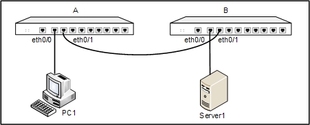
Target: Establishing a tunnel between Device A and B. PC1 is a host behind Device A, with the IP address 188.1.1.2 and gateway 188.1.1.1; Server1 is the server behind Device B, with IP address 10.110.8.210 and gateway 10.110.88.220. The goal of this configuration example is to protect the communication between the subnet of PC1 (188.1.1.0/24) and the subnet of Server1 (10.110.88.0/24), using the method of route-based VPN. Use ESP as the security protocol, 3DES as the encryption algorithm, SHA1 as the hash algorithm and DEFLATE as the compression algorithm.
The topology is shown below:
To establish the VPN tunnel, take the steps below:
Step 1: Configure interfaces
Device A
- On the Navigation pane, click Configure > Network > Network to visit the Network page.
- Select ethernet0/0 from the interface list, and then click Edit. In the Interface Configuration dialog, modify according to your need:
- Binding zone: Layer 3 zone
- Zone: trust
- Type: Static IP
- IP address: 188.1.1.1
- Netmask: 255.255.255.0
- Click OK to save the settings and return to the Network page.
- Select ethernet0/1 from the interface list, and then click Edit. In the Interface Configuration dialog, modify according to your need:
- Binding zone: Layer 3 zone
- Zone: untrust
- Type: Static IP
- IP address: 192.168.1.2
- Netmask: 255.255.255.0
- Click OK to save the settings and return to the Network page.
Device B
- On the Navigation pane, click Configure > Network > Network to visit the Network page.
- Select ethernet0/0 from the interface list, and then click Edit. In the Interface Configuration dialog, modify according to your need:
- Binding zone: Layer 3 zone
- Zone: trust
- Type: Static IP
- IP address: 10.110.88.220
- Netmask: 255.255.255.0
- Click OK to save the settings and return to the Network page.
- Select ethernet0/1 from the interface list, and then click Edit. In the Interface Configuration dialog, modify according to your need:
- Binding zone: Layer 3 zone
- Zone: untrust
- Type: Static IP
- IP address: 192.168.1.3
- Netmask: 255.255.255.0
- Click OK to save the settings and return to the Network page.
Step 2: Configure a tunnel name VPN1
Device A
- On the Navigation pane, click Configure > Network > IPSec VPN to visit the IPSec VPN page to visit the IPSec VPN page.
- Click New on the upper-left of Manual Key VPN List. In the Manual Key VPN Configuration dialog, configure the options as below.
- Tunnel name: VPN1
- Mode: Tunnel
- Peer address: 192.168.1.3
- Local SPI: 0007
- Remote SPI: 0008
- Interface: ethernet0/1
- Protocol: ESP
- Encryption: 3DES
- Inbound encryption key: abcd
- Outbound encryption key: efgh
- Hash: SHA-1
- Inbound hash key: 1234
- Outbound hash key: 5678
- Compression: Deflate
- Click OK to save the settings.
Device B
- On the Navigation pane, click Configure > Network > IPSec VPN to visit the IPSec VPN page to visit the IPSec VPN page.
- Click New on the upper-left of Manual Key VPN List. In the Manual Key VPN Configuration dialog, configure the options as below:
- Tunnel name: VPN1
- Mode: Tunnel
- Peer address: 192.168.1.2
- Local SPI: 0008
- Remote SPI: 0007
- Interface: ethernet0/1
- Protocol: ESP
- Encryption: 3DES
- Inbound encryption key: efgh
- Outbound encryption key: abcd
- Hash: SHA-1
- Inbound hash key: 5678
- Outbound hash key: 1234
- Compression: Deflate
- Click OK to save the settings.
Step 3: Configure routes
Device A
- On the Navigation pane, click Configure > Network > Routing to visit the Routing page.
- On the Destination Route tab, click New. In the Destination Route Configuration dialog, configure the options as below:
- Destination: 10.110.88.220
- Subnet mask: 255.255.255.0
- Next hop: Gateway
- Gateway: 192.168.1.3
- Click OK to save the settings.
Device B
- On the Navigation pane, click Configure > Network > Routing to visit the Routing page.
- On the Destination Route tab, click New. In the Destination Route Configuration dialog, configure the options as below:
- Destination: 188.1.1.0
- Subnet mask: 255.255.255.0
- Next hop: Gateway
- Gateway: 192.168.1.2
- Click OK to save the settings.
Step 4: Configure policy rules
Device A
- On the Navigation pane, click Configure > Security > Policy to visit the Policy page.
- Click New. In the Policy Configuration dialog, configure the options as below:
- Src zone : trust
- Src address: Any
- Dst zone: untrust
- Dst address: Any
- Service: Any
- Action: Security connection From tunnel (VPN) > VPN1
- Click OK to save the settings.
Device B
- On the Navigation pane, click Configure > Security > Policy to visit the Policy page.
- Click New. In the Policy Configuration dialog, configure the options as below:
- Src zone : trust
- Src address: Any
- Dst zone: untrust
- Dst address: Any
- Service: Any
- Action: Security connection From tunnel (VPN) > VPN1
- Click OK to save the settings.
- Click New again. In the Policy Configuration dialog, configure the options as below:
- Src zone: untrust
- Src address: Any
- Dst zone: trust
- Dst address: Any
- Service: Any
- Action: Security connection From tunnel (VPN) > VPN1
- Click OK to save the settings.
When the settings above are completed, the security tunnel between Device A and Device B has been successfully established. Then, the data transmission between the subnet (188.1.1.0/24) and subnet (10.110.88.0/24) is encrypted.