- On the Navigation pane, click Configure > Network > Network to visit the Network page.
- Click New on the upper-left of the interface list.
- Select PPPoE Interface from the drop-down list.
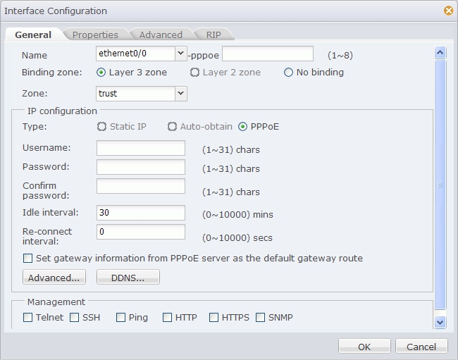
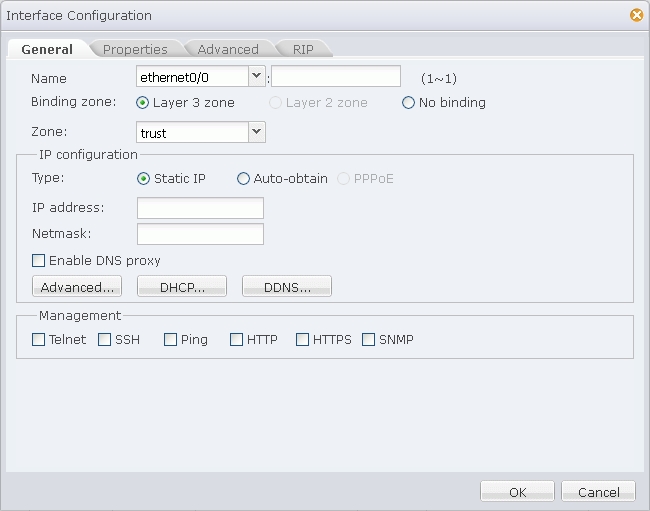
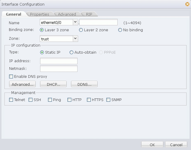
- In the Interface Configuration dialog shown above, specify a name and binding type. If Layer 3 zone is selected, also select a security zone from the Zone drop-down list.
- In the IP Configuration section, configure IP related information for the interface. For detailed options, see the following instructions:
Username: Specifies a username for PPPoE.
Password: Specifies PPPoE user's password.
Confirm password: Enter the password again to make confirmation.
Idle interval: If the PPPoE interface has been idling (no traffic) for a certain period, i.e., the specified idle interval, system will disconnect the Internet connection; if the interface requires Internet access, system will connect to Internet automatically. The value range is 0 to 10000 minutes. The default value is 30.
Re-connect interval: Specifies a re-connect interval (i.e., system will try to re-connect automatically after being disconnected for the interval). The value range is 0 to 10000 seconds. The default value is 0, which means the function is disabled.
Set gateway information from PPPoE server as the default gateway route: With this check box selected, system will set the gateway information provided by PPPoE server as the default gateway route.
Advanced: In the Advanced dialog, configure advanced options for PPPoE, including:
Access concentrator - Specifies a name for the concentrator.
Authentication - Security appliance will have to pass PPPoE authentication when trying to connect to a PPPoE server. The supported authentication methods include CHAP, PAP and Any (the default, anyone between CHAP and PAP). Click an authentication method.
Netmask - Specifies a netmask for the IP address obtained via PPPoE.
Static IP - You can specify a static IP address and negotiate to use this address to avoid IP change. To specify a static IP address, type it into the box.
Service - Specifies allowed service. The specified service must be the same with that provided by the PPPoE server. If no service is specified, system will accept any service returned from the server automatically.
Distance - Specifies a route distance. The value range is 1 to 255. The default value is 1.
Weight - Specifies a route weight. The value range is 1 to 255. The default value is 1.
DDNS: In the DDNS Configuration dialog, configure DDNS options for the interface. For detailed instructions, see Configuring a DDNS. - Specify a management method for the interface. In the Management section, select one or more management method check boxes.
- If needed, click the Properties tab to configure properties for the interface. For detailed options, see the following instructions:
MTU: Specifies a MTU for the interface. The value range is 1280 to 1500/1800 bytes. The default value is 1500. The max MTU may vary from different system models.
ARP learning: Select the Enable check box to enable ARP learning.
ARP Timeout: Specifies an ARP timeout for the interface. The value range is 5 to 65535 seconds. The default value is 1200.
Keep Alive IP: Specifies an IP address that receives the interface's Keep alive packets. - If needed, click the Advanced tab to configure advanced options for the interface, including Shutdown and Monitor and Backup options. For detailed options, see the following instructions:
Function Configuration Shutdown System supports interface shutdown. You can not only enforce to shut down a specific interface, but also control the time of shutdown by schedule, or control the shutdown according to the link status of tracked objects. Configure the options as below:
- Select the Shut down check box to enable interface shutdown.
- To control the shutdown by schedule or tracked objects, select an appropriate check box, and then select an appropriate schedule or tracked object from the drop-down list.
Monitor and Backup Configure the options as below:
- Select an appropriate check box, and then select an appropriate schedule or tracked object from the drop-down list.
- Select an action: Shut down the interface: During the time specified in the schedule, or when the tracked object fails, the interface will be shut down and its related route will fail; Migrate traffic to backup interface: During the time specified in the schedule, or when the tracked object fails, traffic to the interface will be migrated to the backup interface. In such a case you need to select a backup interface from the Backup interface drop-down list and type the time into the Migrating time box. (Migrating time, 0 to 60 minutes, is the period during which traffic is migrated to the backup interface before the primary interface is switched to the backup interface. During the migrating time, traffic is migrated from the primary interface to the backup interface smoothly. By default the migrating time is set to 0, i.e., all the traffic will be migrated to the backup interface immediately.)
- If needed, click the RIP tab to configure RIP for the interface. For detailed options, see the following instructions:
Authentication mode: Specifies a packet authentication mode for the system, including plain text (the default) and MD5. The plain text authentication, during which unencrypted string is transmitted together with the RIP packet, cannot assure security, so it cannot be applied to the scenarios that require high security.
Authentication string: Specifies a RIP authentication string for the interface.
Transmit version: Specifies a RIP information version number transmitted by the interface. By default V2 RIP information will be transmitted.
Receive version: Specifies a RIP information version number received by the interface. By default V2 RIP information will be received.
Split horizon: Select the Enable check box to enable split horizon. With this function enabled, routes learned from an interface will not be sent from the same interface, in order to avoid routing loop and assure correct broadcasting to some extent. - Click OK to save your settings.
- On the Navigation pane, click Configure > Network > Network to visit the Network page.
- Click New on the upper-left of the interface list.
- Select Tunnel Interface from the drop-down list.
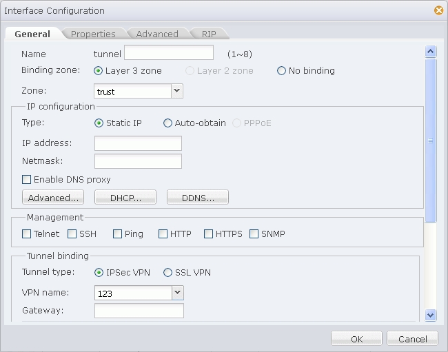
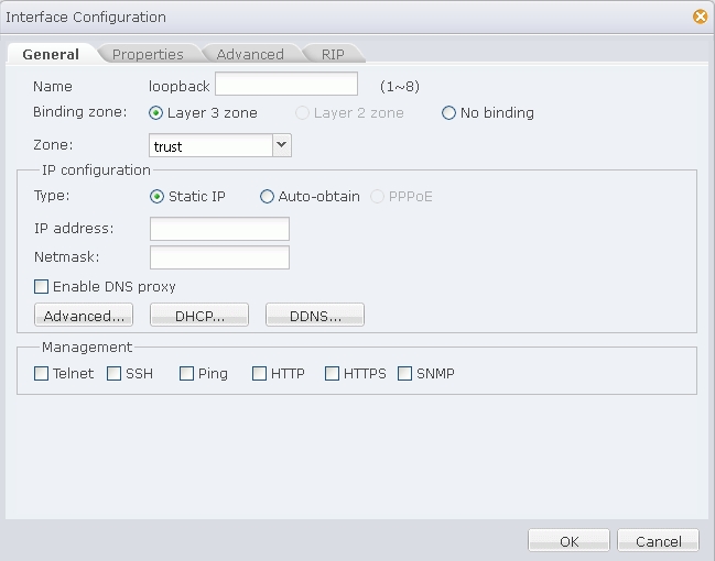
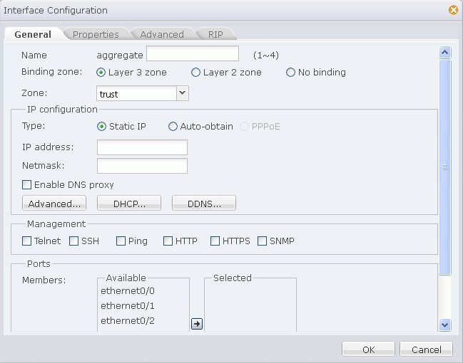
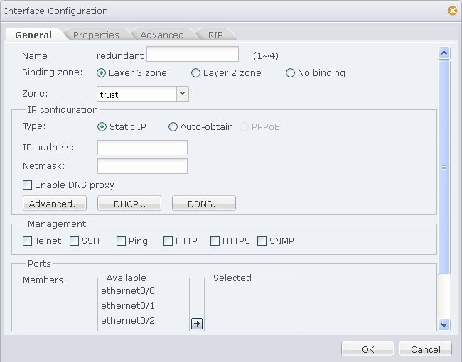
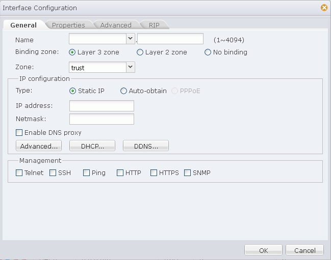
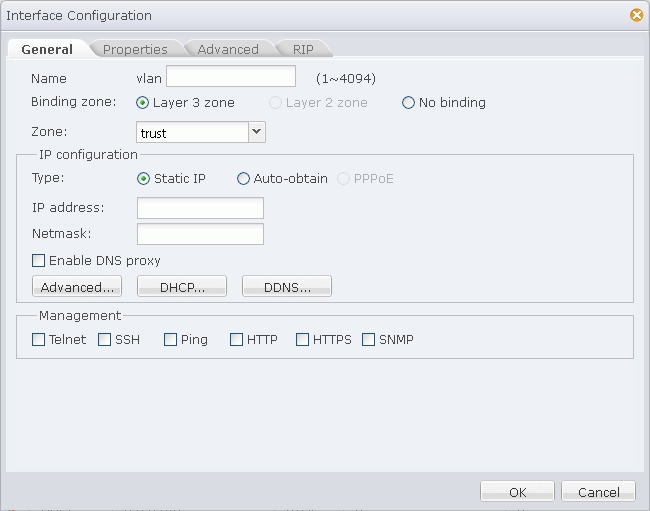
- In the Interface Configuration dialog shown above, specify a name and binding type. If Layer 3 zone is selected, also select a security zone from the Zone drop-down list.
- In the IP Configuration section, configure IP related information for the interface. The IP addresses for the interface can be static, or dynamically allocated. For detailed options, see the following instructions:
Type Description Static IP IP address: Specifies an IP address for the interface. Netmask: Specifies a netmask for the interface. Enable DNS Proxy: Select this check box to enable DNS proxy for the interface. Advanced Management IP: Specifies a management IP for the interface. Type the IP address into the box. Secondary IP: Specifies secondary IPs for the interface. Type IP addresses into the IP address 1 and IP address 2 boxes. DHCP: In the DHCP Configuration dialog, configure DHCP related options for the interface. For detailed instructions, see Configuring DHCP. DDNS: In the DDNS Configuration dialog, configure DDNS related options for the interface. For detailed instructions, see Configuring a DDNS. Auto-obtain Set gateway information from DHCP server as the default gateway route: With this check box selected, system will set the gateway information provided by the DHCP server as the default gateway route. Advanced Distance: Specifies a route distance. The value range is 1 to 255. The default value is 1. Weight: Specifies a route weight. The value range is 1 to 255. The default value is 1. Management Priority: Specifies a priority for the DNS server. Except for static DNS servers, system can also learn DNS servers dynamically via DHCP or PPPoE. Therefore, you need to configure priorities for the DNS servers, so that the system can choose a DNS server according to its priority during DNS resolution. The priority is represented in numbers from 1 to 255. The larger the number is, the higher the priority is. The priority of static DNS servers is 50. DDNS: In the DDNS Configuration dialog, configure DDNS related options for the interface. For detailed instructions, see Configuring a DDNS. - Management. In the Management section, select one or more management method check boxes.
- In the Tunnel Binding section, bind the interface to a IPSec VPN tunnel or a SSL VPN tunnel. One tunnel interface can be bound to multiple IPSec VPN tunnels, while only to one SSL VPN tunnel. For more information on the tunnel binding configuration, see the following instructions:
After selecting a tunnel type and name, click Add and the binding information will be displayed in the list below. To delete a binding, select an entry from the list and click Delete.Tunnel Type Description IPSec VPN VPN name: Specifies a name for the IPSec VPN tunnel that is bound to the interface. Gateway: Specifies a next-hop address for the tunnel, which can be either the IP address or the egress IP address of the peering tunnel interface. This parameter, which is 0.0.0.0 by default, is only valid when multiple IPSec VPN tunnels should be bound to the tunnel interface. SSL VPN VPN name: Specifies a name for the SSL VPN tunnel that is bound to the interface. - If needed, click the Properties tab to configure properties for the interface. For detailed options, see the following instructions:
MTU: Specifies a MTU for the interface. The value range is 1280 to 1500/1800 bytes. The default value is 1500. The max MTU may vary from different system models.
ARP learning: Select the Enable check box to enable ARP learning.
ARP Timeout: Specifies an ARP timeout for the interface. The value range is 5 to 65535 seconds. The default value is 1200.
Keep Alive IP: Specifies an IP address that receives the interface's Keep alive packets. - If needed, click the Advanced tab to configure advanced options for the interface, including Shutdown and Monitor and Backup options. For detailed options, see the following instructions:
Function Configuration Shutdown System supports interface shutdown. You can not only enforce to shut down a specific interface, but also control the time of shutdown by schedule, or control the shutdown according to the link status of tracked objects. Configure the options as below:
- Select the Shut down check box to enable interface shutdown.
- To control the shutdown by schedule or tracked objects, select an appropriate check box, and then select an appropriate schedule or tracked object from the drop-down list.
Monitor and Backup Configure the options as below:
- Select an appropriate check box, and then select an appropriate schedule or tracked object from the drop-down list.
- Select an action: Shut down the interface: During the time specified in the schedule, or when the tracked object fails, the interface will be shut down and its related route will fail; Migrate traffic to backup interface: During the time specified in the schedule, or when the tracked object fails, traffic to the interface will be migrated to the backup interface. In such a case you need to select a backup interface from the Backup interface drop-down list and type the time into the Migrating time box. (Migrating time, 0 to 60 minutes, is the period during which traffic is migrated to the backup interface before the primary interface is switched to the backup interface. During the migrating time, traffic is migrated from the primary interface to the backup interface smoothly. By default the migrating time is set to 0, i.e., all the traffic will be migrated to the backup interface immediately.)
- If needed, click the RIP tab to configure RIP for the interface. For detailed options, see the following instructions:
Authentication mode: Specifies a packet authentication mode for the system, including plain text (the default) and MD5. The plain text authentication, during which unencrypted string is transmitted together with the RIP packet, cannot assure security, so it cannot be applied to the scenarios that require high security.
Authentication string: Specifies a RIP authentication string for the interface.
Transmit version: Specifies a RIP information version number transmitted by the interface. By default V2 RIP information will be transmitted.
Receive version: Specifies a RIP information version number received by the interface. By default V2 RIP information will be received.
Split horizon: Select the Enable check box to enable split horizon. With this function enabled, routes learned from an interface will not be sent from the same interface, in order to avoid routing loop and assure correct broadcasting to some extent. - Click OK to save your settings.